 |
WTH-CS/F-B |
| www.watchfuleyesolutions.com | Surge Protection Monitoring System |
|
WTH-CS/F-B |
| www.watchfuleyesolutions.com | Surge Protection Monitoring System |
 Main features:
1.Real-time monitoring of the operational status of Surge Protective Devices(SPDs) :once the SPD fault occurs, a warning message will be issued promptly.
2. Real-time monitoring of lightning and surge; once a lightning strike or surge occurs, a warning message will be issued immediately, and the lightning and surge will be measured at the same time. 3. Real-time monitoring of the local system voltages: once the system fault occurs, it can act as a black box for analyzing causes. 4. Networking functions: data is transmitted through 232 and 485 dual channels, making the data safe and reliable. It can also be extended to wireless GPRS, WiFi or RJ45 network connection, making the networking more convenient. 5. Cloud Storage: with cloud service extension, all the data is stored on the cloud servers for a month, and can be set to be saved for an additional period at the critical monitoring points. 6. Unattended operation: through any computer connected to the Internet, log onto the cloud platform to view the system mode, achieving remote monitoring office work. WTH-CS/F-B - Page 02
 VIP Functions:
1. Regular inspection: during regular inspection by technical maintenance personnels, press the inspection button on the device to record the inspection time in the server.
2. Alarm transmission: once an SPD fault, lightning or surge occurs, a sound and light warning message will be issued, and a warning E-mail can also be sent. 3. Internet of things: each device has a unique serial number. Since an unlimited number of nodes are available on the same network, using the software enables centralized management for multi-users. 4. Cloud servers and online hosting: based on the world's top Amazon cloud server in the US, it can ensure 365X24 working conditions and the maximum online working time. The online hosting service frees you from being concerned about system routine maintenance and reduces system maintenance costs. Note: please log onto Cloud Service for a 30-day free VIP cloud service experience, WTH-CS/F-B - Page 03
 Applications in the following places:
Electric power distribution center
Banking network center Telecommunications network center Highway machine room Highway tollbooth control center Government network center Education and scientific research room or laboratory Public security and video monitoring center Radio and television network center Commercial power distribution center High-rise elevator control room Residential property video and fire−surveillance center WTH-CS/F-B - Page 04
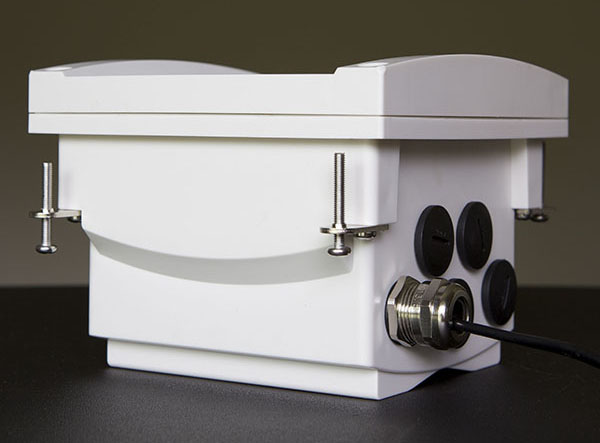
 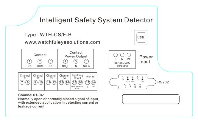 The Applications of Ports:
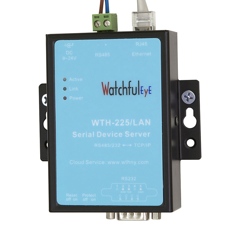
USB interface: for hardware program upgrade
232 interface: for serial ports communication, extending GPRS wireless communication or RJ45 Ethernet. Equipment power supply:110-230VAC (50-60Hz), displaying the voltage of the devices, (D6 interfaces , analog) The Application of Upper Six Terminals:
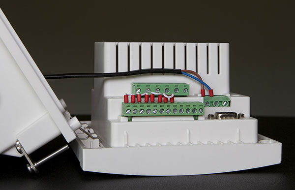
1-2-3: remote signal output; 1-2 is normally open signal, 2-3 is normally closed signal (D12 interface switch)
4-5-6: remote signal output, 4-5 is normally a closed signal; under normal circumstances, the power output is 110/220V. Once a fault occurs, there are no voltage outputs; 5-6 is normally an open signal, under the normal circumstances, no voltage outputs. Once a fault occurs, output is110/220 (D13 interface switch) The application of the lower 12 terminals:
7-8: the operational condition of Class I SPD (D1 interfaces, analog switch can be used to monitor the leakage current 1 , current monitoring , switch )
9-10: the operational condition of Class II SPD (D2 interfaces, analog switch can be used to monitor the leakage current 2 , current monitoring , switch ) 11-12: the operational condition of Class III SPD (D3 interfaces, analog switch can be used to monitor the leakage current 3 , current monitoring , switch ) 13-14: the operational condition of the terminal SPD (D4 interfaces, analog switch can be used to monitor the leakage current 4 , current monitoring , switch ) 15-16: for the Lightning Counting (D11 interface, switch ) 17-18: 485 communications, fixed Note: the switching of D1 \ D2 \ D3 \ D4 can be used for the applications of inputting the switch signals of smoke alarms, tilt alarm, etc. WTH-CS/F-B - Page 05
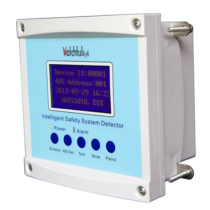
Simple Device Panel
Standby LCD screen display:
1. Device number ( unique ) 2. 485 address number (allow custom settings with the figures between 1 and 247) 3. Time and date: yyyy-mm-dd, hh-mm 4. Logo: WATCHFUL EYE Two Indicator Lights:
1. "Power" light, green indicates power and working properly
2. "Alarm" light, red indicates system failure Five Main Buttons:
1. Browse button: the system monitors 20 channels of data with four channels data per page; each time you press the scroll screen, D1-20 system monitoring data will display in a cycle ( depending on the system, some channels are empty ). Continuing pressing for 2 seconds is the setting function of the system administrator, switching to the pages for setting to browse the data of 20 channels, press each time to browse the setting data of the next channels.
2. 485 Set: 1-247 settings of 485 address , continue pressing for two seconds each time, circularly flash one-hundred , ten and single digits, press the button once at the time of flashing , then the corresponding number will plus 1; press it until the desired address is set. Press any other key to save the data and exit setting, the screen displays the standby mode. In the case of not pressing any operation for 30 seconds, data can be auto-saved, and the screen displays the standby mode. 3. Test button: Press once to send a bunch of system default data; in the situation of receiving the data of debugging network, continuing pressing for 2 seconds is the setting function of the system administrator, cyclically setting the interval to send data: 0 seconds ( do not send data ) , 10 seconds, 20 seconds, 30 seconds, 60 seconds , 180 seconds , 300 seconds 4. Mute button: once the system alarms, press this button to stop alarm, and the alarm indicator light will not turn off. Continuing pressing the button for 2 seconds is the setting function of the system administrator to clear the number of lightning counts to 0. 5.Patrol button: in the alarming state, press the button for a short time to clear the alarm indicator light and transmit the inspection records and information; if in the normal state, press it for a short time to send inspection record information. Continuing pressing for 2 seconds is the setting function of the system administrator to initialize its system settings to the factory state. WTH-CS/F-B - Page 06
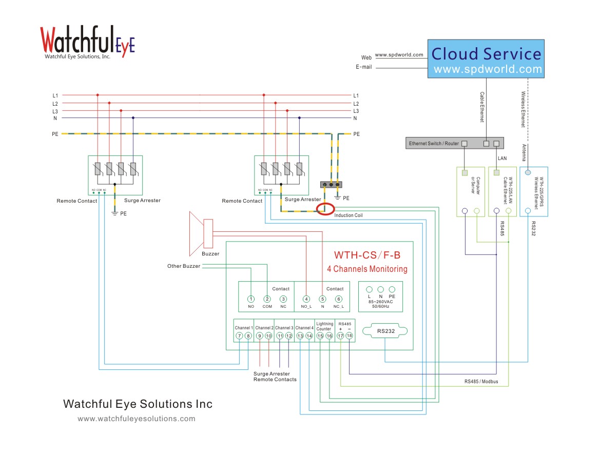
Solutions:
 |