Paperless Datasheet
Going green and protecting environment is manufacturers' responsibility. Each WatchfulEyE product has a link of downloading data sheet on its enclosure:
http://datasheet.watchfuleyesolutions.com/US120174.html
3D file download
Model & Ordering Code
| Model |
Ordering Code |
MCOV/Uc |
Remote Contacts |
UPC/EAN Code |
| WTH-20/D/R/3P+NPE-275 |
US120174 |
275VAC |
YES |
- |
| WTH-20/D/3P+NPE-275 |
US120164 |
NO |
- |
| WTH-20/D/R/3P+NPE-320 |
US120175 |
320VAC |
YES |
- |
| WTH-20/D/3P+NPE-320 |
US120165 |
NO |
- |
| WTH-20/D/R/3P+NPE-385 |
US120176 |
385VAC |
YES |
- |
| WTH-20/D/3P+NPE-385 |
US120166 |
NO |
- |
| WTH-20/D/R/3P+NPE-420 |
US120177 |
420VAC |
YES |
- |
| WTH-20/D/3P+NPE-420 |
US120167 |
NO |
- |
Certificates of Products
Description
In accordance with: IEC/EN61643-11 - Class III and UL1449 Type 4 Location
Location of use: branch sub-distribution boards
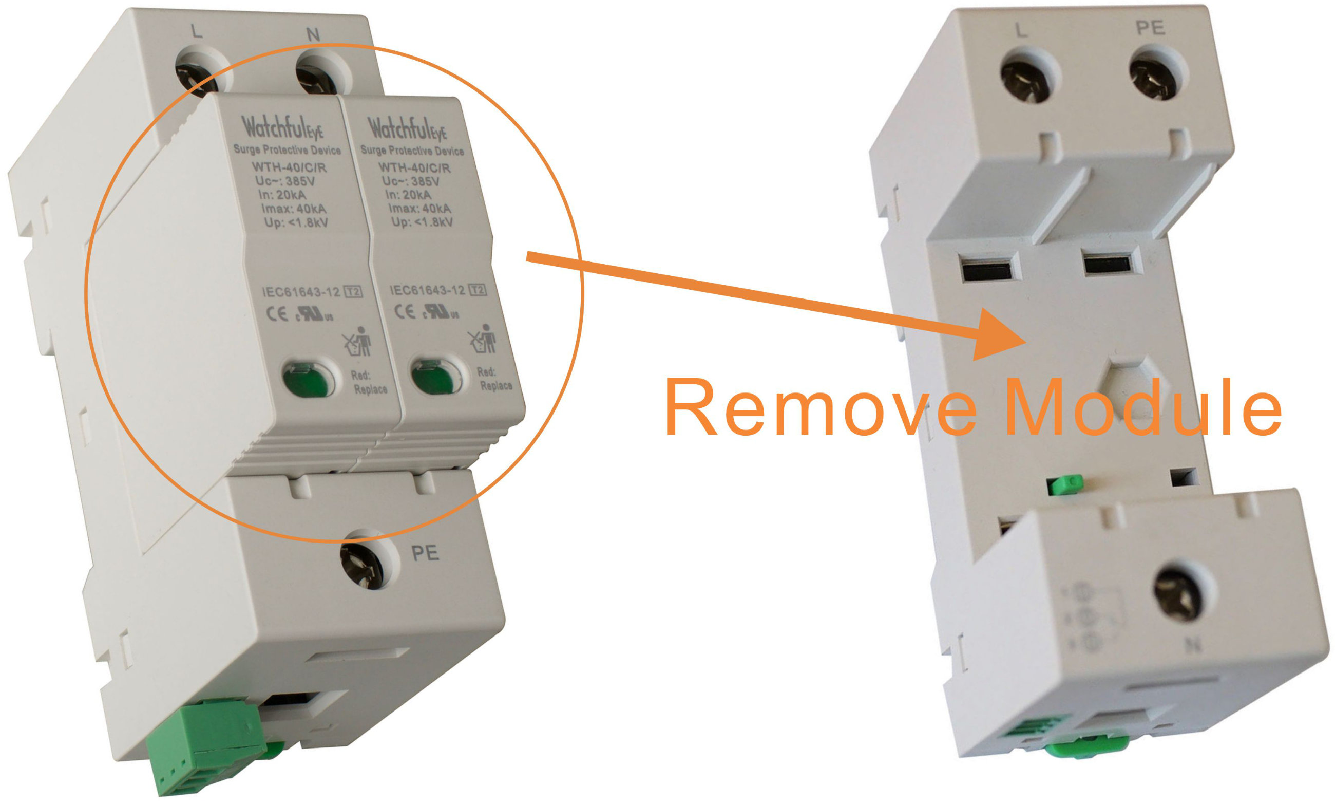
Plug-in module and separate base design enables convenient maintenance.
Internal thermal disconnect devices help ensure safe or at end-of-life
| Maximum Continuous Operating Voltage (MCOV/Uc) |
275VAC |
320VAC |
385VAC |
420VAC |
| Voltage Protection Level (Up @L-N) |
1.3kV |
1.4kV |
1.5kV |
1.7kV |
| Residual Voltage (Ures @L-N) |
1.0kV |
1.1kV |
1.2kV |
1.4kV |
N-PE Module
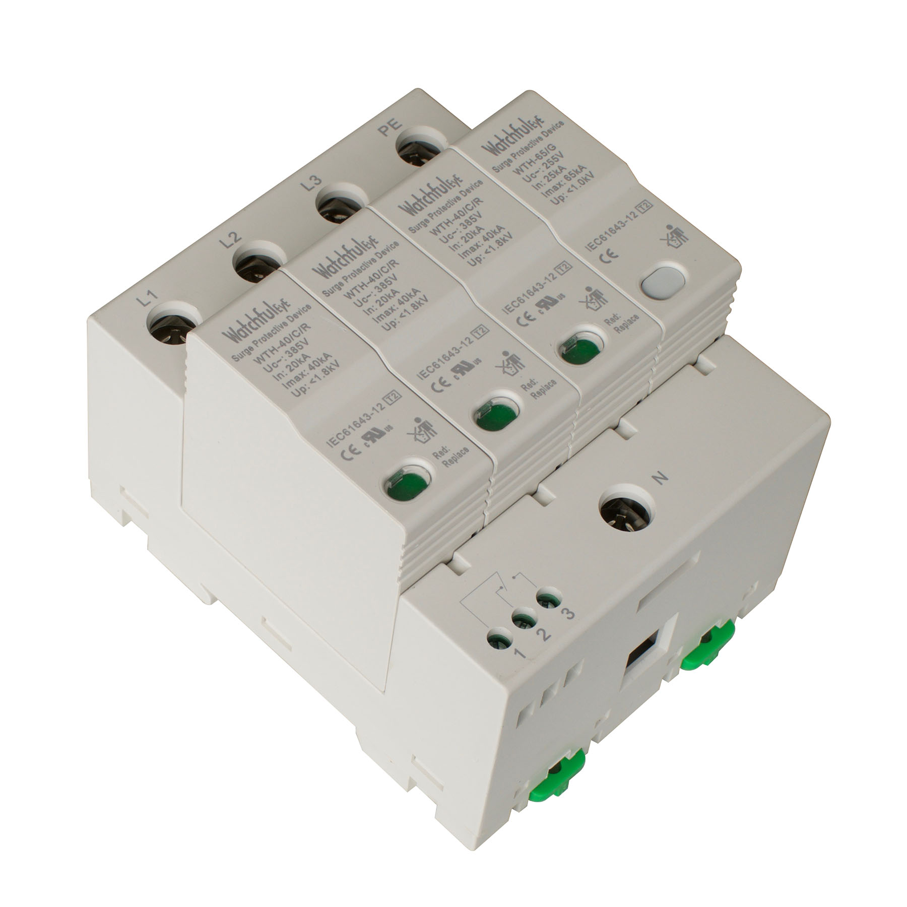
WTH-65/G module integrates High-Energy GDT, no leakage current. It pairs WTH-40/C/R series surge protector, combined into N-PE protection mode, the two modules are the same in dimension and shape, and are connected with a dedicated bus-bar to achieve a perfect combination.
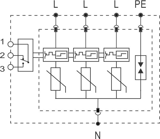
Surge Protection Connection Diagram
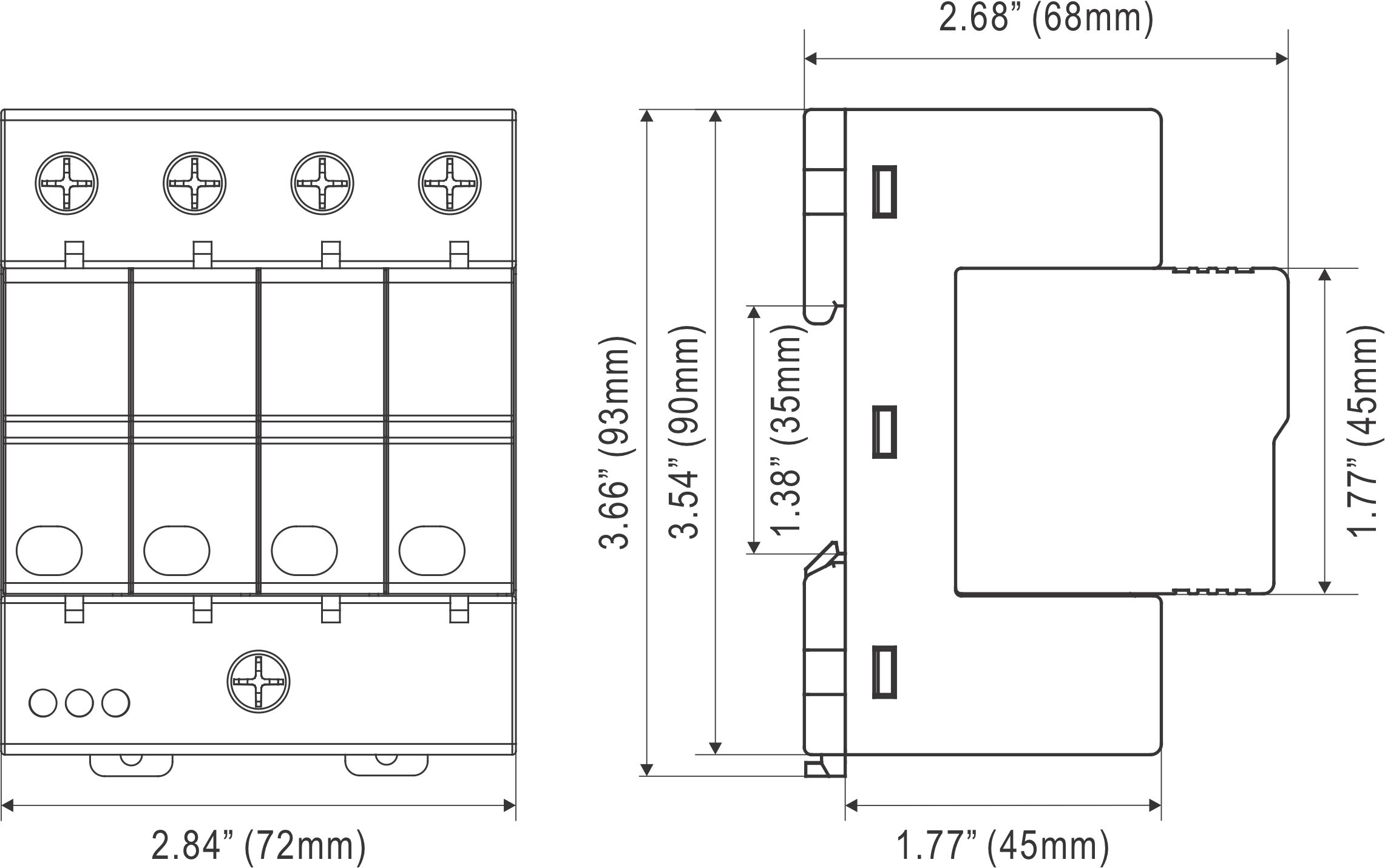
Dimensions
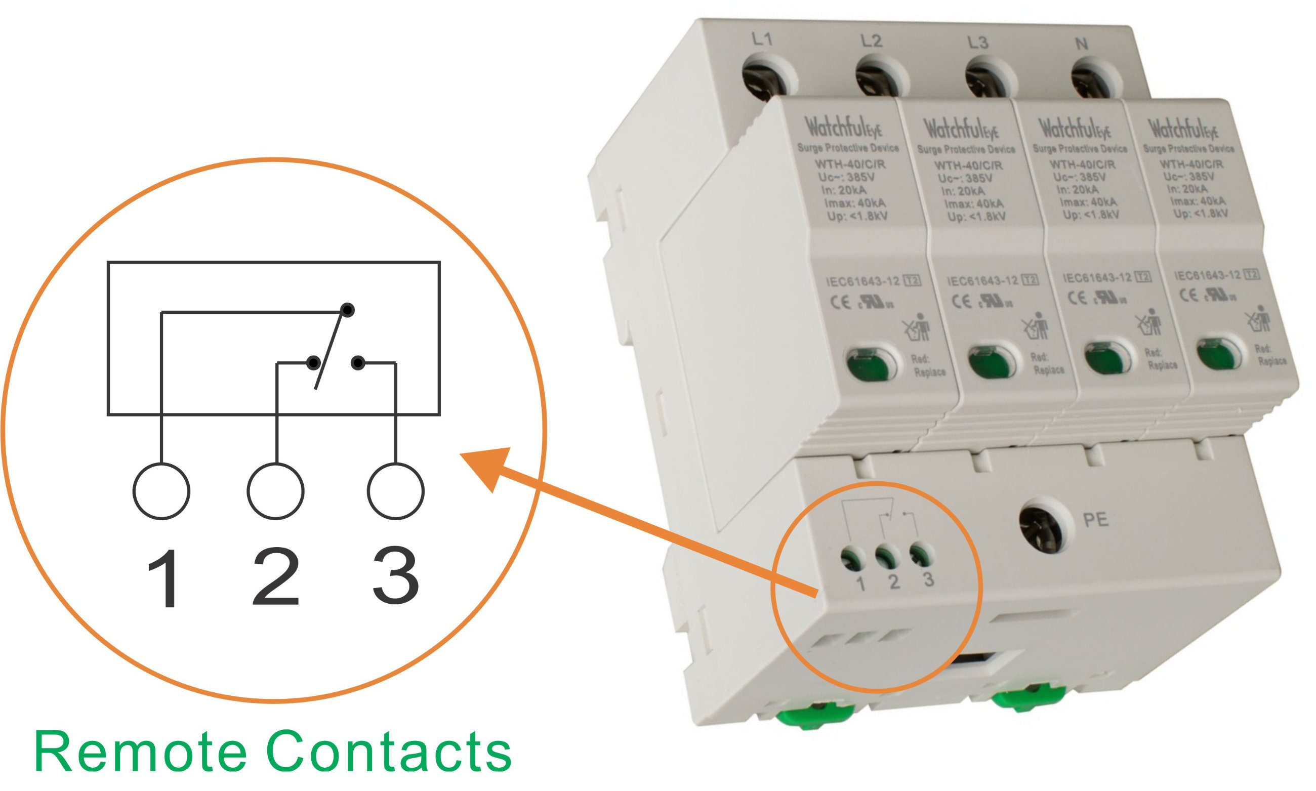
Remote Contacts (Dry Contacts)
1: COM (Common)
2: NC (Normally Close)
3: NO (Normally Open)
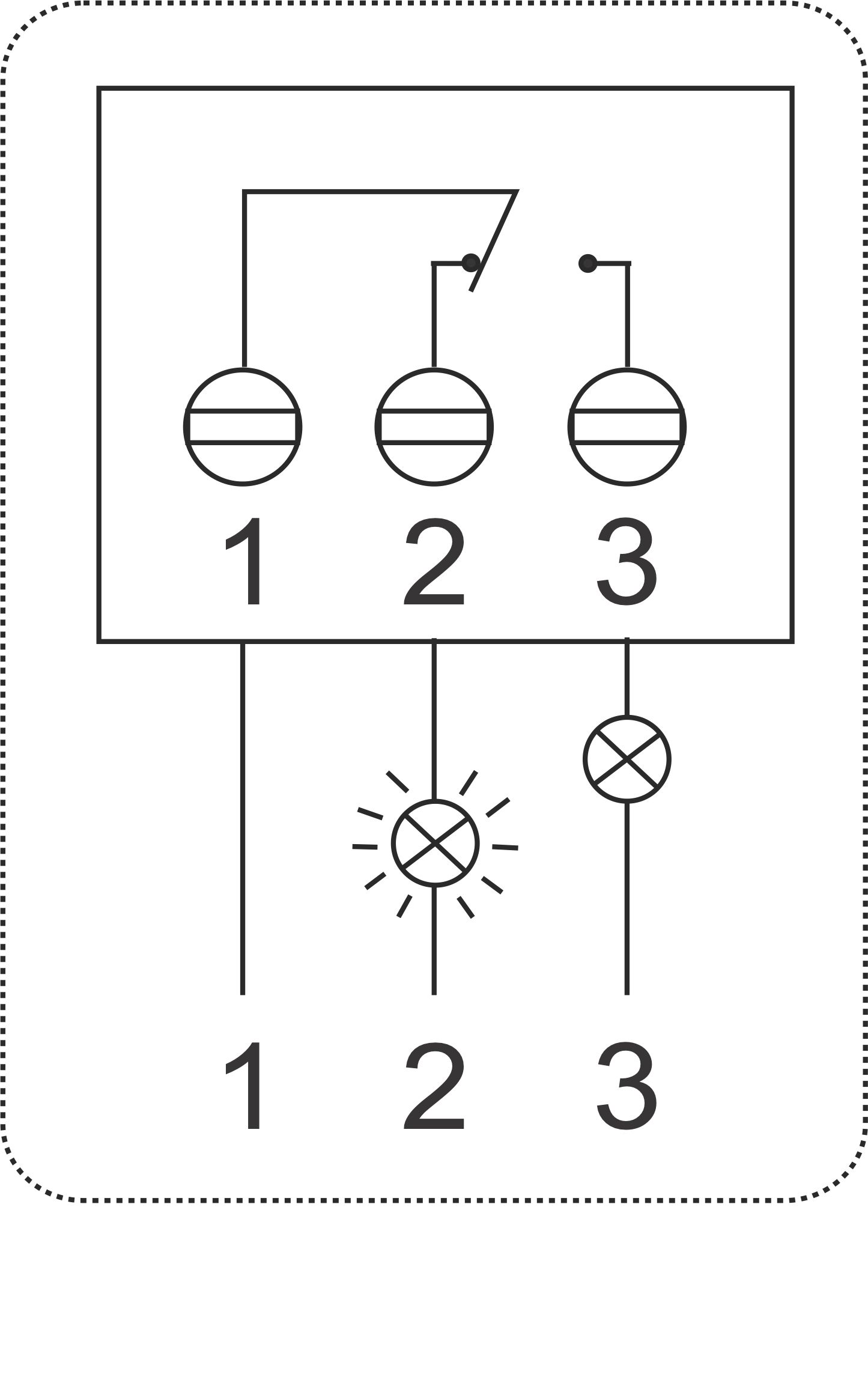
| Contact Ratings |
125VAC/3A, 250VAC/1.5A |
| Terminal Cross Section |
Max. 1.5mm² |
| Stripping Length Contacts |
0.25 inches (6-7mm) |
| Remote Terminal Torque |
0.25Nm |
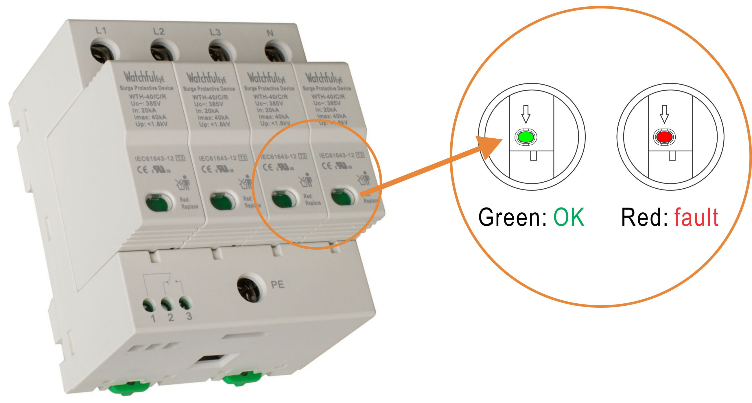
Fault Indication (same indication in 1P/2P/3P/4P/1P+NPE/3P+NPE models)
Common Terms and Definitions
1. Normal operating voltage rating (Un)
2. Maximum Continuous Operating Voltage (Uc/MCOV):
Maximum r.m.s. voltage, which may be continuously applied to the surge protective device's mode of protection.
3. Nominal Discharge Current for Class II Test (In):
crest value of the current through the surge protective device having a current waveshape of 8/20μs.
4. Maximum Discharge Current (Imax):
Crest value of a current through the surge protective device having an 8/20μs waveshape and magnitude according to the manufacturers specification. Imax is equal to or greater than In.
5. Voltage Protection Level (Up):
Maximum voltage to be expected at the surge protective device terminals due to an impulse stress with defined voltage steepness and an impulse stress with a discharge current with given amplitude and waveshape.
6. Residual Voltage (Ures):
Crest value of voltage that appears between the terminals of an surge protective device due to the passage of discharge current.
7. IEEE 62.41
CATEGORY C: outdoor overhead lines, service entrance (most severe)
CATEGORY B: major feeder, short branch circuits, service panel (indoor)
CATEGORY A: long branch circuits, receptacles (indoor) (least severe)
How to choose a suitable Uc(MCOV) value
Note: Uc >1.15Un
The relationship between two parameters Uc and Up of a surge protective device is proportional.
If Uc is small, the value of Up is also small; surge protective devices with smaller Up can provide better surge protection.
Whether to choose smaller Uc depends on the voltage stability of the grid.
If you choose surge protective devices with smaller Uc for the grid with instable voltage, the surge protective devices will frequently work while the grid voltage fluctuates, resulting in shortening surge protective device's product life.
If you choose larger Uc, and the value of Up is accordingly large, the surge protective efficiency will not be so fine.
If you are unsure of the voltage stability of the grid,
it is suggested to calculate MCOV(Uc) using the following formula: √ 2
Un < Uc < √ 3 Un
| AC Network (Un) |
MCOV(Uc), L/N-PE Protection Mode |
| 110V, 120/208V, 127/220V |
150V |
| 220/380V |
275V, 320V, 385V |
| 230/400V |
275V, 320V, 385V, 420V |
| 240/415V |
320V, 385V, 420V |
| 266/460V, 277/480V |
385V, 420V |
| 347/600V |
550V, 690V |
| Wind Power System |
690V (Grid side ), 885V (Gen side ) |
AC Network Connection Diagram (1/2)
AC Network Connection Diagram (2/2)
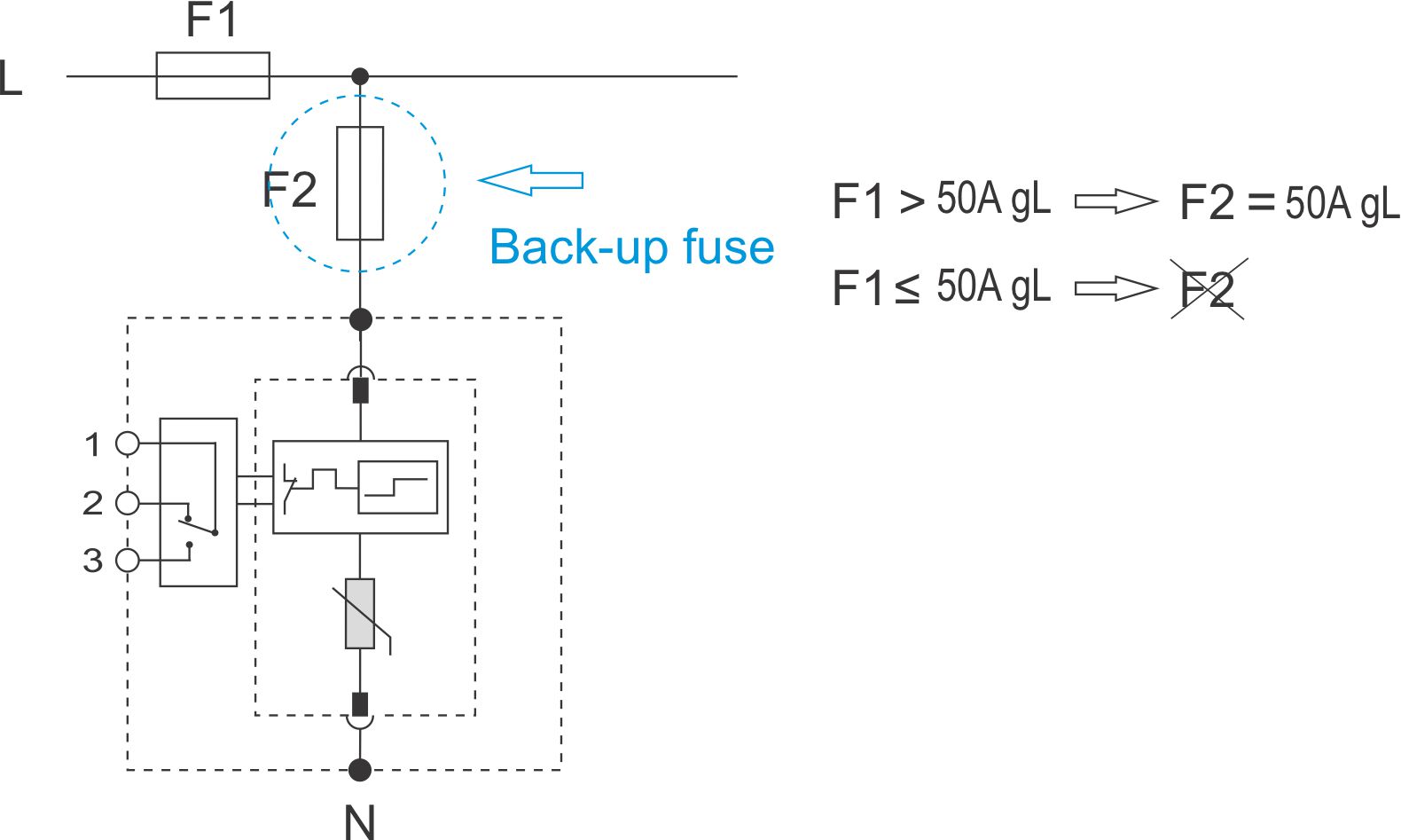
Selection of back-up fuse
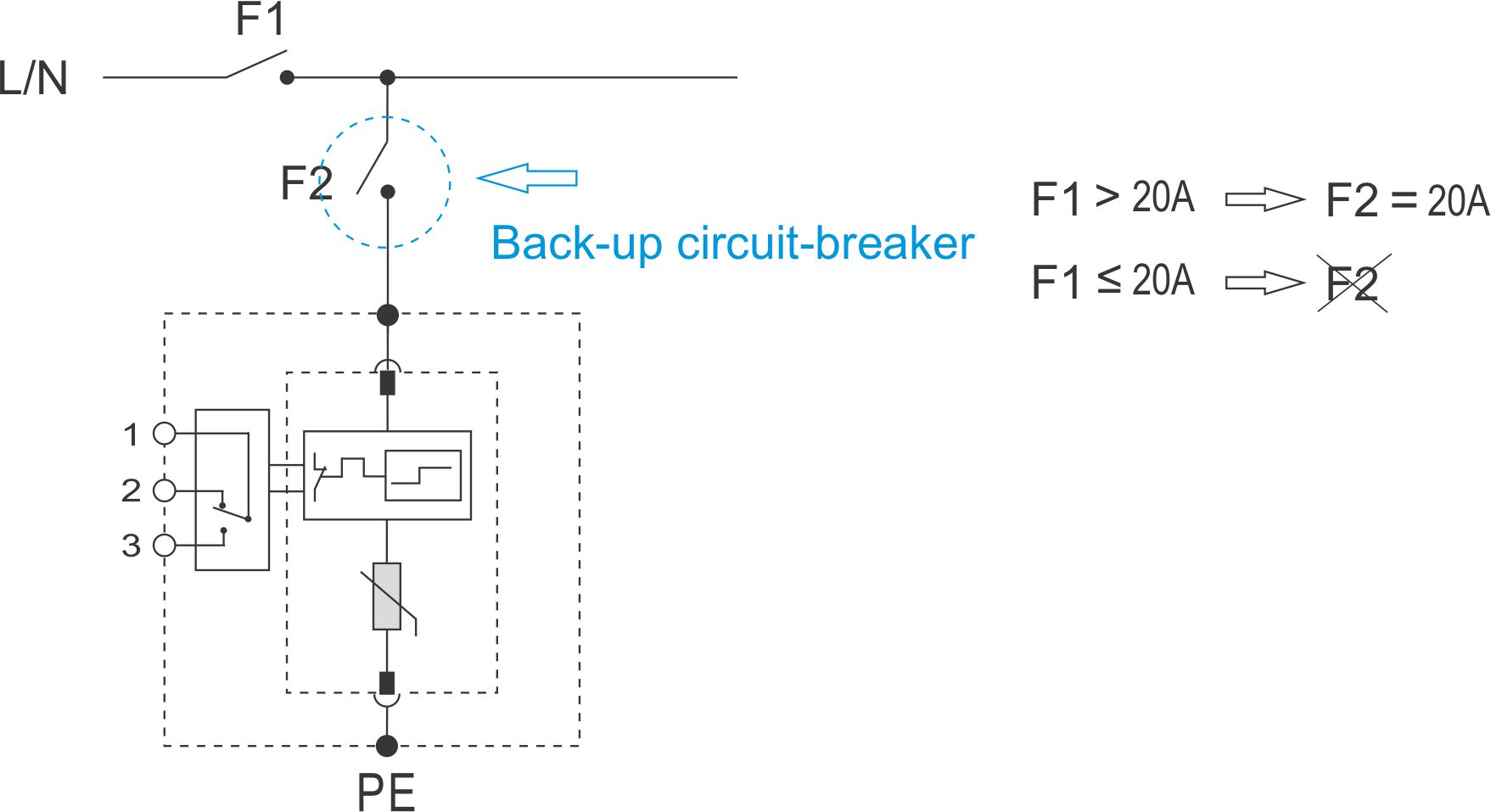
Selection of back-up circuit-breaker
Application
Key
1. Origin of the installation
2. Distribution board
3. Distribution outlet
4. Main earthing terminal or bar
5. Surge protective device, class I or II tested
6. Earthing connection (earthing conductor) of the surge protective device
7. Fixed equipment to be protected
8. Surge protective device, class II tested
9. Surge protective device, class II or class III tested
10. Decoupling element or line length
F1, F2, F3 overcurrent protective disconnectors
NOTE Refer to IEC 61643-12 for further information.
FAQ & Help
1. What should I do if I can't find the paper manual in the product packaging?
Watchful Eye products is committed to going green with paperless data sheets. On the side of each product enclosure is an engraved link with URL for downloading paperless data sheet and QR code of the website. If you need the paper data sheet, you can open the link and print the data sheet by yourself.
2. The advantages of fault indication windows?
If surge protection fails, the fault indication windows will turn red, thus it can be seen intuitively, and the surge protective device can be replaced in time to avoid damage to the equipment caused by a second surge.
3. What instruments can be used to test whether its surge protection function is normal or not?
Test with a Watchful Eye surge protector tester
4. How to connections of the SPD?
Please refer to the standard IEC 60364-5-53
Connecting conductors of SPDs:
Conductors between the SPD and the main earthing terminal or the protective conductor shall have a cross-sectional area not less than:
- 6 mm² copper or equivalent for class Il tested SPDs installed at or near the origin of the
installation;
- 16 mm² copper or equivalent for class I tested SPDs installed at or near the origin of the installation.
a) L/N to surge protector copper recommended diameter: 7AWG (10mm² ), minimum: 6mm²
b) surge protector to PE copper recommended diameter: 5AWG (16mm² ), minimum: 10mm²
(a+b) ≤ 0.5m
5. Can you list more applications?
Power supply panel, whole house
Download WatchfulEyE Official App
To learn about more products and updates from company, please scan QR code to download the official App:

After-sale Services
Watchful Eye provides a 5-year quality warranty globally.

