Of all similar SPD testers, it is probably the lightest,
smallest tester with the most accurate test data
and the most durable battery
Working Principle of a Surge Protective Device
The core component of a surge protector is a nonlinear component inside. According to the different nonlinear components, surge protectors can be classified as switch-type (the core component is mainly GDT) and voltage-limiting type (the core component is mainly MOV).
Although the working principles of GDT and MOV are different, the basic characteristics are very similar: when there is no over voltage, their impedance is very high, generally megohm level, which is almost equivalent to an open circuit. When an over voltage occurs, the impedance quickly drops to a few ohms, and the surge current will flow into the ground through the surge protector instead of entering the equipment. At the same time, as the impedance of the surge protector at this time is small, the voltage on both sides is also relatively small, and it is connected in parallel with the protected equipment, it also prevents the equipment from withstanding large surge voltages. In this way, it has the effect of draining and limiting the pressure.
Importance of Leakage Current Parameters
With the extension of the service life of the voltage-limiting surge protector, the gradual aging of the MOV chip will be accompanied by an increase in leakage current. The increase in leakage current will cause overheating, accelerated aging, and failure of the surge protector.
If we do not pay attention to the aging curve of the surge protector and replace it in time, once the surge protector cannot disconnect in time when getting overheating due to increasing in leakage current, it will more likely cause an explosion, and more seriously, it may cause a fire.
Importance of Break-over Voltage Parameters
The break-over voltage of surge protector is the voltage value measured when the current flowing through the surge protector is 1 mA when the test voltage increases.
Has the surge protector in the system been broken down?
Can the SPD which has been used for years continue to be used?
If the L-PE voltage of the power grid system is 277V, is the selected surge protector correct?
Normally only the value of UC is marked on the surge protector. What is the actual break-over voltage in response to the surge current?
All of problems above will be solved when break-over voltage parameters are measured.
WatchfulEye Solutions specializes in developing and manufacturing a complete range of surge protective devices(SPDs), protecting your equipment and systems against surge caused by lightning inductive voltage or operational over voltages.
Watchful Eye surge protective devices are widely used in low voltage DC & AC power supply system, data and control system in telecommunication and new energy industry such as solar and wind power system, etc.
UL certificate for power supply series:
UL File number:E345944
UL certificate for networking & signal series:
UL File number:E346881
CE Certificate:
Certificate number for power supply series:1048140519 Certificate for networking & signal series:1044270319
RoHS Certificate:
RoHS for power supply series:STT/15T1037-RoHS RoHS for Networking and signal series:STT/15T1036-RoHS
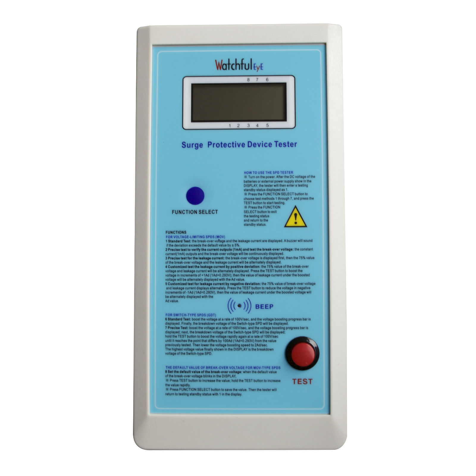
WTH-CS/BT-1000V portable handheld LCD display Break-over Voltage Leakage current tester for surge protective device applies to the measurement of the parameters of the voltage-limiting type and switch-type SPDs. These data are used for evaluating the operating characteristics of the SPDs and the product selection to cooperate with the construction site.
Main Features of WTH-CS/BT-1000V SPD Tester:
1. Portable and convenient use with batteries, rechargeable batteries or external power supply; suitable for office and onsite measurements
2. Easy, rapid and precise measurement by pressing one button for testing and immediate display SPD data features
3. While MOV testing, a buzzer will sound if the deviation of break-over voltage exceeds the default value by ± 5%.
4. While MOV testing, a buzzer will sound if the leakage current exceeds 20 μA.
5. Applied to testing both MOV-type and GDT- type SPDs
6. Precise break-over voltage test under the constant current 1mA
7. Precise leakage current test under 75% of the break-over voltage
8. The voltage of the tester can be boosted up to 1000V DC
9.Convenient multimeter calibration methods
Conformity of Test Result
The breakover voltage of surge protective device refers to the value of the voltage which is tested when 1mA current flows through the surge protective device while the testing voltage is boosted.
Since only the value of Uc is marked on the label of a surge protection product, the breakover voltages of the products specified in corresponding with the Uc values by different manufacturers during actual production maybe vary. The following are the parameters of "Watchful Eye" surge protective devices for reference.
Ⅰ. Rapid testing methods for voltage-limiting type(MOV-type) SPDs:
Choose FUNCTION 1, press TEST button, Break-over Voltage and Leakage Current will display on the screen.
Ⅱ. Rapid Testing methods for switch-type(GDT-type) SPDs:
Choose FUNCTION 6, press the testing button, “Breakdown Voltage” will display on the screen.
Technical Specification of WTH-CS/BT-1000V:
Range of break-over voltage for testing Un(U1mA): 120~200 +/-5V, 200~1000V +/-2.5%
Range of leakage current for testing: 0~20.0uA +/-0.5uA, 20.0~25.0uA +/-2.5%
FUNCTION 1 testing mode: for testing voltage-limiting type SPDs, break-over voltage and leakage current will display in about 2.5 seconds.
Range of breakdown voltage for testing: 0~1000V, ±2.5%, ±5V(120-1000V)
FUNCTION 6 testing mode: for testing switch-type SPDs, boost the DC voltage step by step at a rate of 100V/second for an accurate measurement of breakdown voltage.
Minimum resolution of the break-over Voltage: 1V
Minimum resolution of the leakage current: 0.1μA
Operation temperature: 32°F ~ +122°F (0°C ~ +50°C)
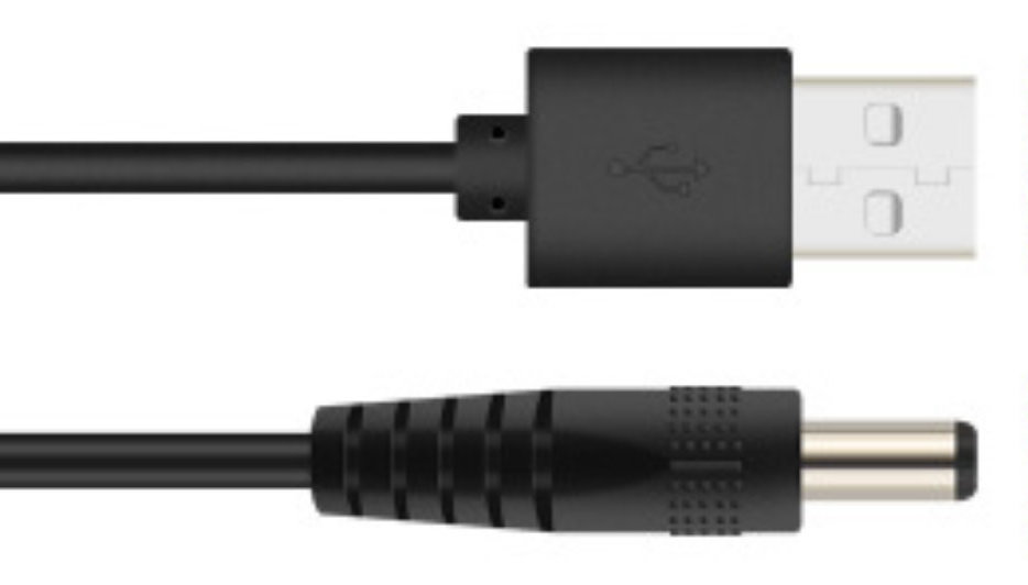
Power supplies: four AA1.2V rechargeable batteries, four AA1.5V batteries or DC 5V 2A power supply adapter
Weight: 570g/1.26 lb (Without accessories)
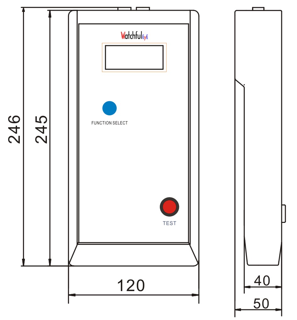
Dimensions: 245mm×120mm×50mm(9.65in×4.72in ×1.97in)
Accessories
Dimensions
1. banana head test cable; 2. pin test pen; 3. crocodile clip
1. USE EXTREME CAUTION In the testing process, the voltage boosts up to above 1000V, and the maximum current is 1mA. DO NOT touch the exposed part of the test banana plug or the test pens.
2. DO NOT press the TEST button when the tester isn’t connected to a tested sample. Doing so can damage the tester.
3. ALWAYS turn off the power supply promptly during the long standby mode prompting.
4. ALWAYS do the testing strictly according to the operation instructions. Non-qualified persons are not allowed to do the calibration or open the tester without professional guidance.
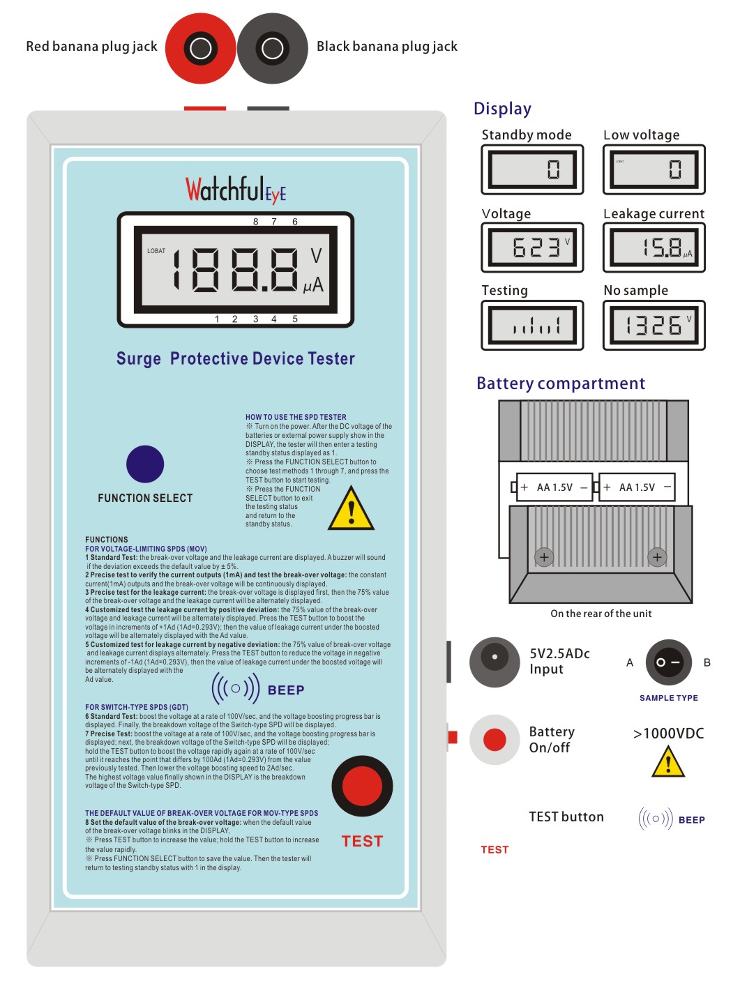
Power Supply of the SPD Tester
There are two power supply modes:
1. Connect to DC 5V 2A power supply adapter, plug in the power supply, the initial value "0" will display on the screen, that is the standby mode.
2. Install 4 AA batteries or rechargeable batteries, press the red button on the right side to turn on the battery power supply switch, the voltage of the batteries will display on the screen first, and then display the initial value "0", that is the standby mode.
Note:
1. If the voltage is lower than 4.5V, the upper left corner of the screen will display "Lobat".
2. If the standby time exceeds 300 seconds(every 300 seconds interval), the tester will emit a continuous sound of "Beep.Beep" to remind you of shutting down to save energy, avoiding running out of batteries due to long-time standby.
Test Error
If the test error is in the unacceptable range, calibrate to the common voltage segments and critical leakage current, e.g., if a calibration for the 500V voltage segment is applied in a 300V voltage segment test, it will result in errors.
Test Banana Plugs and Test Pens
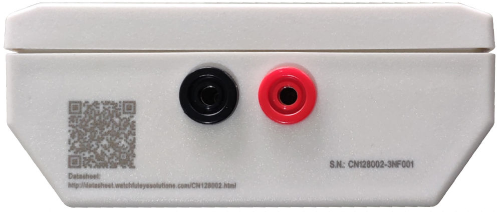
1. There are two test banana plug jacks on the top of the tester, insert the red and black test banana plugs into the corresponding colored jacks.
2. The test pens include a clip type and a probe type. The other ends of the two test banana plugs can be put on test clips or test probes according to the test requirements (e.g., use the clip-type test pens for testing SPD modules without bases).
3. Take out the SPD module to be tested
4. Clamp the two poles of the voltage-limiting(MOV-type) SPD with the test clips.
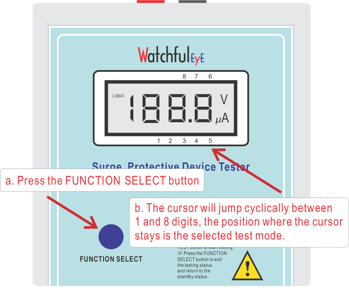
Test Preparation and Selection of Testing Modes
Set the mode button according to the tested SPD sample type.
Note:
if a default value of break-over voltage is set, test an SPD with FUNCTION 1 testing method, a long BUZZER will sound If the deviation of the tested value exceeds the default value by ± 5%.
Take WTH-40/C/R/1P-385 as the tested sample of voltage-limiting(MOV-type) SPD
Take WTH-65/G/1P-255 as the tested sample of switch-type(GDT-type) SPD
FOR VOLTAGE-LIMITING SPDS (MOV-TYPE)
1 Standard Test: the break-over voltage and the leakage current are displayed. A buzzer will sound if the deviation exceeds the default value by ± 5%.
2 Precise test to verify the current outputs (1mA) and test the break-over voltage: the constant current(1mA) outputs and the break-over voltage will be continuously displayed.
3 Precise test for the leakage current: the break-over voltage is displayed first, then the 75% value of the break-over voltage and the leakage current will be alternately displayed.
4 Customized test the leakage current by positive deviation: the 75% value of the break-over voltage and leakage current will be alternately displayed. Press the TEST button to boost the voltage in increments of +1Ad (1Ad=0.293V); then the value of leakage current under the boosted voltage will be alternately displayed with the Ad value.
5 Customized test for leakage current by negative deviation: the 75% value of break-over voltage and leakage current displays alternately. Press the TEST button to reduce the voltage in negative increments of -1Ad (1Ad=0.293V), then the value of leakage current under the boosted voltage will be alternately displayed with the Ad value.
FOR SWITCH-TYPE SPDS (GDT-TYPE)
6 Standard Test: boost the voltage at a rate of 100V/sec, and the voltage boosting progress bar is displayed. Finally, the breakdown voltage of the Switch-type SPD will be displayed.
7 Precise Test: boost the voltage at a rate of 100V/sec, and the voltage boosting progress bar is displayed; next, the breakdown voltage of the Switch-type SPD will be displayed; hold the TEST button to boost the voltage rapidly again at a rate of 100V/sec until it reaches the point that differs by 100Ad (1Ad=0.293V) from the value previously tested. Then lower the voltage boosting speed to 2Ad/sec. The highest voltage value finally shown in the DISPLAY is the breakdown voltage of the Switch-type SPD.
THE DEFAULT VALUE OF BREAK-OVER VOLTAGE FOR MOV-TYPE SPDS
8 Set the default value of the break-over voltage: when the default value of the break-over voltage blinks in the DISPLAY,
※ Press TEST button to increase the value; hold the TEST button to increase the value rapidly.
※ Press FUNCTION SELECT button to save the value. Then the tester will return to testing standby status with 1 in the display.
1. Function Selection Choose FUNCTION 1
2. Testing
Press TEST button, release the button when a BEEP sounds.
3. Read the testing data
The screen displays the break-over voltage and the leakage current under 75% of the break-over voltage of the tested MOV-type SPD; the whole process takes about 2.5 seconds.
4. Continue to test
1) According to the features of the MOV, it is normal that data inconsistency may occur between the first test and the second test, this characteristic of MOVs can be judged by the data from several more tests.
2) When the leakage current displays on the screen, press the TEST button; you’ll hear a "Beep". After the first test is completed, the second test will start automatically.
3) Also, when the screen returns to the "0" standby mode, press the TEST button to start the second test.
4. Exit to the standby mode
When the leakage current displays on the screen, in 1 second without any key operation, the screen will be cleared to "0" and will exit the test to return to standby mode.
Test with The Default Value of Break-over Voltage
1. Function Selection
Choose FUNCTION 8
2. Set the default value of the break-over voltage: when the default value of the break-over voltage blinks in the DISPLAY
※ Press TEST button to increase the value; hold the TEST button to increase the value rapidly.
※ Press FUNCTION SELECT button to save the value. Then the tester will return to testing standby status with 1 in the display.
3. Standard test with a default value of break-over voltage
The break-over voltage and leakage current displays, a long BUZZER will sound If the deviation of the tested value exceeds the default value by ± 5%.
Ⅱ. Precise Test and Calibration Mode of Break-Over Voltage
1. Function Selection
Choose FUNCTION 2
2. Test
Press TEST button, release the button when a BEEP sounds.
3. Read the test data
Test the precise value of the break-over voltage until the screen continually displays the tested break-over voltage of the MOV-type SPD, read the test data.
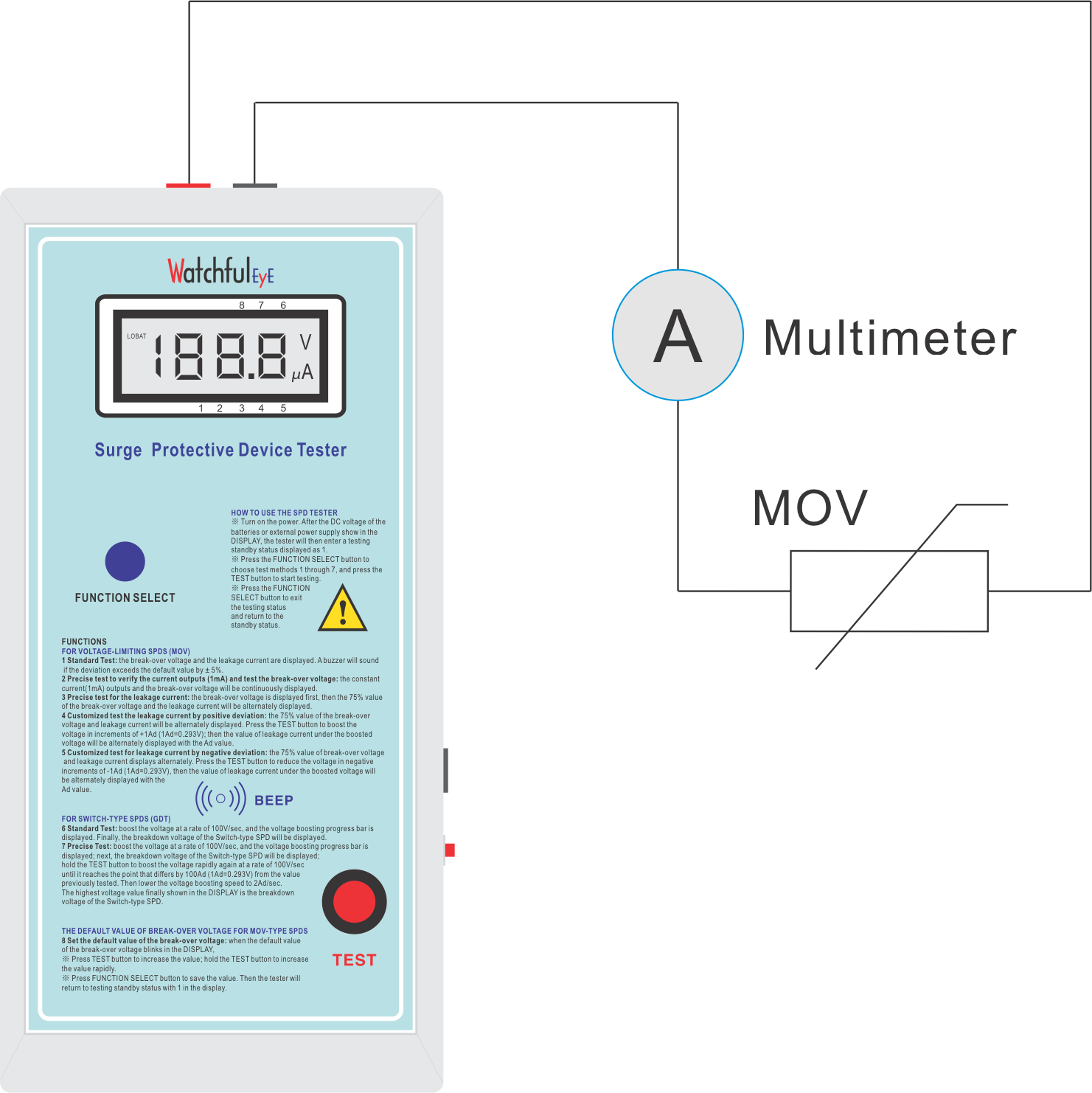
4. Verify the current value of 1mA
1) Choose a multimeter "Fluke 87V" or any other multimeter with an accuracy of 0.1μA. Connect the multimeter in series with the MOV type SPD and the test pens, and verify the constant current output of 1mA.
2) The description of the MOV leakage current is given by the tested voltage value when the constant current is 1mA. According to this characteristic, the more accurate the 1mA constant current outputs, the more accurate the testing data of the break-over voltage will show on the display.
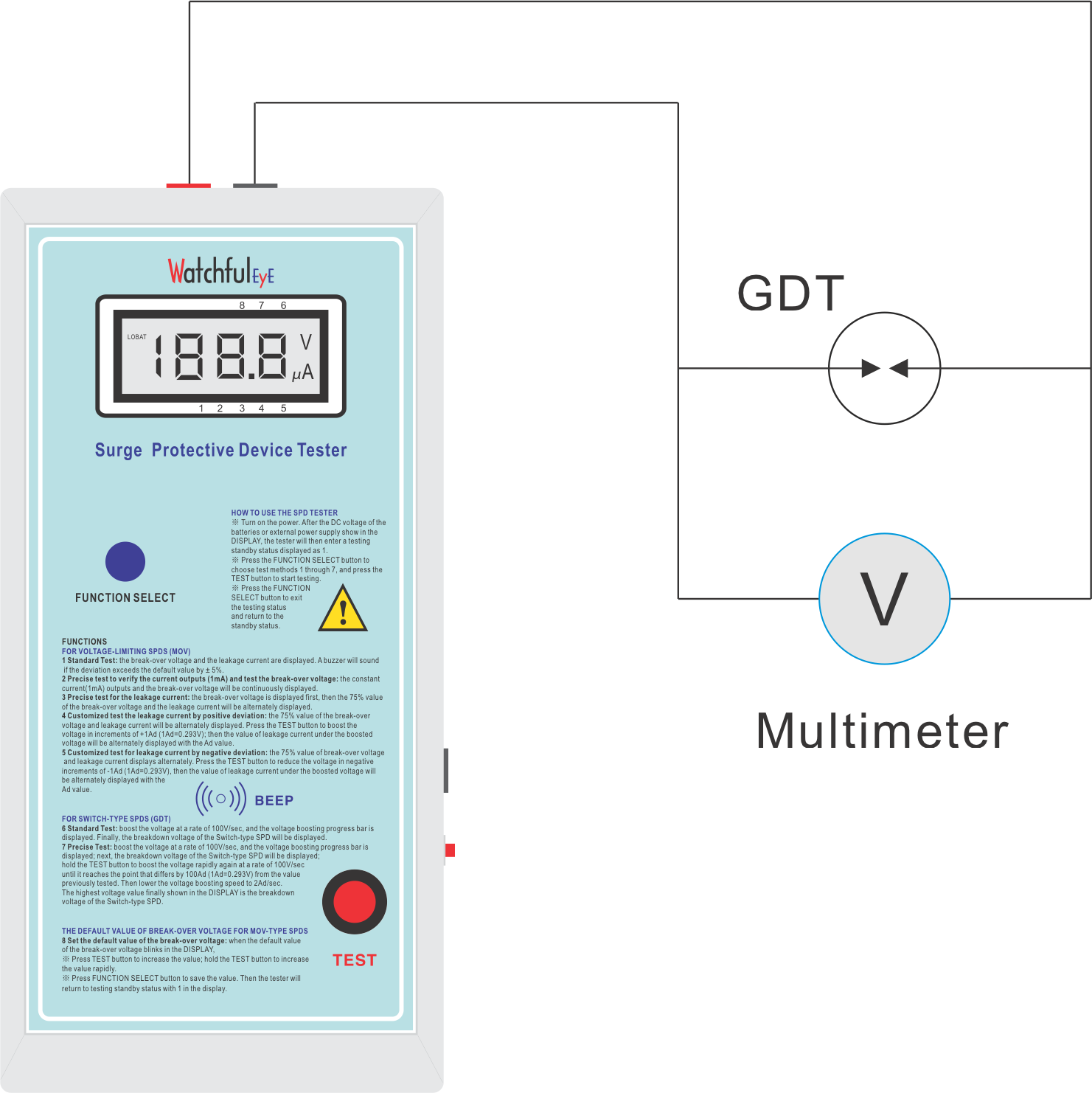
5. The calibration of the break-over voltage
1) Choose a multimeter "Fluke 87V" or any other multimeter with the accuracy of 0.1V.
2) Connect the multimeter probes in parallel with the SPD and the test pens.
3) In this mode, while maintaining the constant current of 1mA outputs, the tester continually displays the break-over voltage value.
4) Open the tester and adjust the tester R3 (Potentiometer) to make the tester display the same value as the multimeter. At this point, the calibration of the break-over voltage is completed.
6. Exit to the standby mode
In the state of displaying the break-over voltage, press the TEST button. When you hear a "Beep". Release the TEST button and the screen will be cleared to "0". Then exit the test to return to the standby mode.
Ⅲ. Precise Test and Calibration of MOV Leakage Current
1. Function Selection
Choose FUNCTION 3
2. Testing
Press TEST button, release the button when a BEEP sounds.
3. Read the test data
The screen displays the break-over voltage of the tested MOV-type SPD, and then followed by the display of the leakage current under 75% of the break-over voltage every 1 second.
4. Precise testing of leakage current
In this mode, the constant voltage is 75% of the break-over voltage outputs. Read the accurate leakage current value of the MOV type SPD.
5. The calibration of 75% of the break-over voltage value
The characteristics of MOV and the error of 75% of the break-over voltage may have a great influence on the accuracy of the leakage current.
1) Choose a multimeter "Fluke 87V" or any other multimeter with an accuracy of 0.1V.
2) Connect the multimeter probes in parallel with the SPD and the test pens.
3) In this mode, the constant voltage is 75% of the break-over voltage outputs. The tester screen continually and alternately displays 75% of the break-over voltage value and the leakage current value as well.
4) Open the tester and adjust the tester R14(Potentiometer) to make the multimeter display the same value as that the tester. At this point, the calibration of 75% of the break-over voltage is completed.
6. The calibration of leakage current
1) Choose a multimeter "Fluke 87V" or any other multimeter with the accuracy of 0.1μA.
2) Connect the multimeter probes in series with the SPD and the test pens.
3) In this mode, the constant voltage is 75% of the break-over voltage outputs. The tester screen continually and alternately displays 75% of the break-over voltage value and the leakage current value as well.
4) Open the tester and adjust the tester R17(Potentiometer) to make the multimeter display the same value as the tester. At this point, the calibration of the leakage current is completed.
7. Exit to the standby mode
In the alternate display mode, press the TEST button, release the button when hearing a sound of "Beep". The screen will be cleared to "0" and exit the test to return to the standby mode.
Ⅳ. Leakage Current Test under the Mode of Fine-Turning "Ad" Voltage
Note: 1Ad=0.293V
1. Function Selection
Choose FUNCTION 4 or 5
2. Testing
Press TEST button, release the button when a BEEP sounds.
3. Read the test data
The screen displays the break-over voltage of the tested MOV-type SPD. This is followed by the screen displaying the leakage current under 75% of the break-over voltage every 1 second.
4. The precise testing of leakage current
In this mode, the constant voltage is 75% of the break-over voltage outputs. Read the leakage current value of the MOV type SPD.
5. Enter the fine-turning voltage testing mode under 75% of the break-over voltage
In the alternate display mode, press the TEST button continually until hearing a sound of "Beep". Release the TEST button, and the screen alternately displays "0" and the leakage current, it enters the fine-turning voltage testing mode.
6. Leakage current testing under the Fine-turning testing "Ad" voltage mode
"0" represents 0Ad, which is the default base value of 75% of the break-over voltage. In this mode, adjust the constant voltage value based on the accuracy of 1Ad=0.293V.
1) Set the mode button to A position and press the TEST button. When hearing a sound of "Beep", each time reduce 1Ad voltage based on 75% of the break-over voltage value. The screen displays the adjusted "Ad" value, and the tester will accurately display the fine-turning constant voltage of the leakage current value.
2) Set the mode button to B position and press the TEST button. When hearing a sound of "Beep", each time boost 1Ad voltage based on 75% of the break-over voltage value. The screen displays the adjusted "Ad" value, and the tester will accurately display the fine-tuning constant voltage of the leakage current value.
7. More instructions of this function
1) According to the characteristics of MOV, the tested leakage current value will be inconsistent under 76%, 75% or 74% of the break-over voltage.
2) This function can test different leakage current values under different voltages more accurately
8. Exit to standby mode
In the test mode of adjusting "Ad" voltage, press the TEST button continually until hearing a sound of "Beep". Release the TEST button and the screen will be cleared to "0" and exit the test to return to standby mode.
1. Function Selection
Choose FUNCTION 6
2. Testing
Press TEST button, release the button when a BEEP sounds.
3. Read the test data
The voltage is boosted at a rate of 100V/s. The screen will then display the breakdown voltage of the tested GDT-type SPD.
4. Exit to the standby mode
In about 1 second without any key operation, the screen will be cleared to "0". At this point, exit the test to the standby mode.
VI Precise Testing and Calibration of Breakdown Voltage
1. Function Selection
Choose FUNCTION 7
2.Slow boosting and calibration with a multimeter
Press the TEST button, and release the TEST button when a BEEP sounds.
3. Read the testing data
The voltage is boosted at the speed of 100V/s. The screen will display the breakdown voltage of the tested GDT-type SPD. Boost the voltage at the same rate again. When the voltage reaches close to the breakdown point of 100Ad, slow down boosting the voltage at a rate less than 1V/second. The screen will keep displaying the corresponding voltage values until the SPD is broken down, after which the breakdown voltage will display on the screen.
4. Calibration Mode of Breakdown Voltage
1) Choose a multimeter "Fluke 87V" or any other multimeter with the accuracy of 0.1V.
2) Connect the multimeter probes in parallel with the SPD and the test pens.
3) In this slow boosting mode, voltage will be boosted at the speed of less than 1V/second. Compare the voltage displayed on the tester screen with the measured voltage from the multimeter.
4) Open the back cover of the tester and adjust the tester R4(Potentiometer) to make the tester display the same value as the multimeter. The calibration of the breakdown voltage is then completed.
5. Exit to the standby mode
The screen will be cleared to "0" and you can exit the test to the standby mode in about 1 second without any key operation.
VII. Help for Tester Measurement (measurement by third-party institutions)
Note: It is recommended to choose a MOV with break-over voltage of 620V ± 5%
1. Verification of current 1mA
(1) Principle: the testing equipment generates a 1mA constant current source
(2) Wiring diagram on the right
(3) Operation steps: Press FUCNTION KEY to select Function 2 (the index on the screen points to 2), then press “TEST KEY to generate current, verify whether the current is 1mA, then press FUNCTION KEY to exit.
2. Verify Voltage
(1) Principle: The testing equipment generates a current of 1mA. When the current of 1mA flows through the varistor, a voltage is generated across the varistor. This voltage is the varistor’s break-over voltage. Different varistors have various break-over voltages
(2) Wiring diagram on the right:
(3) Operation steps: press FUNCTION KEY to select Function 2 (the index on the screen points to 2), then press TEST KEY to generate current, and verify the voltage displayed on the tester with the voltage in calibration table, and then press FUNCTION KEY to exit
3. Verify Leakage Current
(1) Principle: apply 75% of the break-over voltage to both terminals of the varistor. At this time, the current flowing through the varistor is leakage current, which is generally a μA level current.
(2) Wiring diagram on the right:
(3) Operation steps: Press FUNCTION KEY to select Function 3 (the indicator on the screen points to 3), and then press TEST KEY. At this time, the tester generates a 1mA current, measures the break-over voltage of the varistor; then applies 75% of the break-over voltage, the display will alternately show 75% of the break-over voltage and leakage current, then verify the tester leakage current, and then press the FUNCTION KEY to exit
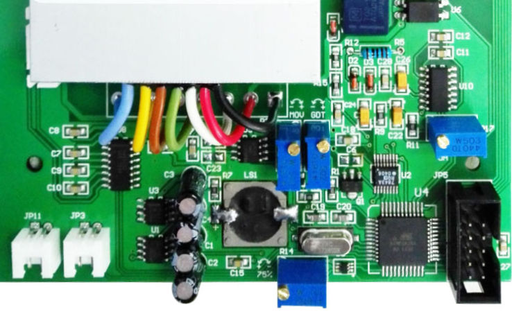
Opened the back cover of the tester with a screwdriver, find the potentiometer R3, R14, R17 and R4 in corresponding to the calibration functions.
Step 1. Calibrate the constant current of 1mA
Choose FUNCTION 2 to calibrate the stability of 1mA current(at current mode of a mutimeter)
Step 2. Calibrate the break-over voltage with R3
Choose FUNCTION 2 to calibrate the break-over voltage of MOV(at voltage mode of a mutimeter)
Step 3. Calibrate 75% of the break–over voltage with R14
Choose FUNCTION 2 to calibrate the 75% of break-over voltage(at voltage mode of a mutimeter)
Step 4. Calibrate the leakage current with R17
Choose FUNCTION 3 to calibrate the leakage current of MOV under 75% of break-over voltage (at voltage mode of a mutimeter)
Step 5. Calibrate the breakdown voltage with R4
Choose FUNCTION 7 to calibrate the breakdown voltage of GDT(at voltage mode of a mutimeter)
Note: R3, R14, R17 and R4 indicate potentiometers
(Open the back cover of an SPD tester with a screwdriver, the blue components in the following picture refer to potentiometers R3, R14, R17 and R4)
1. What should I do if I can't find the paper datasheets in the package?
Watchful Eye fully implements the strategy of going green with paperless data sheets. Each product is engraved with the URL of the paperless instructions and the QR code of the website on the upper side of the product shell where the test line socket is located. If you need paper data sheets, you can open the link and print the online data sheets.
2. What types of surge protectors can the tester detect?
Voltage-limiting surge protector, varistor MOV, switch-type surge protector, discharge tube(GDT), or hybrid surge protector
3. Which parameters are used to detect the surge protector?
The measured parameters are: break-over voltage and leakage current of voltage-limiting surge protector (MOV), breakdown voltage of switch-type surge protector (GDT) or hybrid surge protector
4. Can the surge protector be detected when it is powered on?
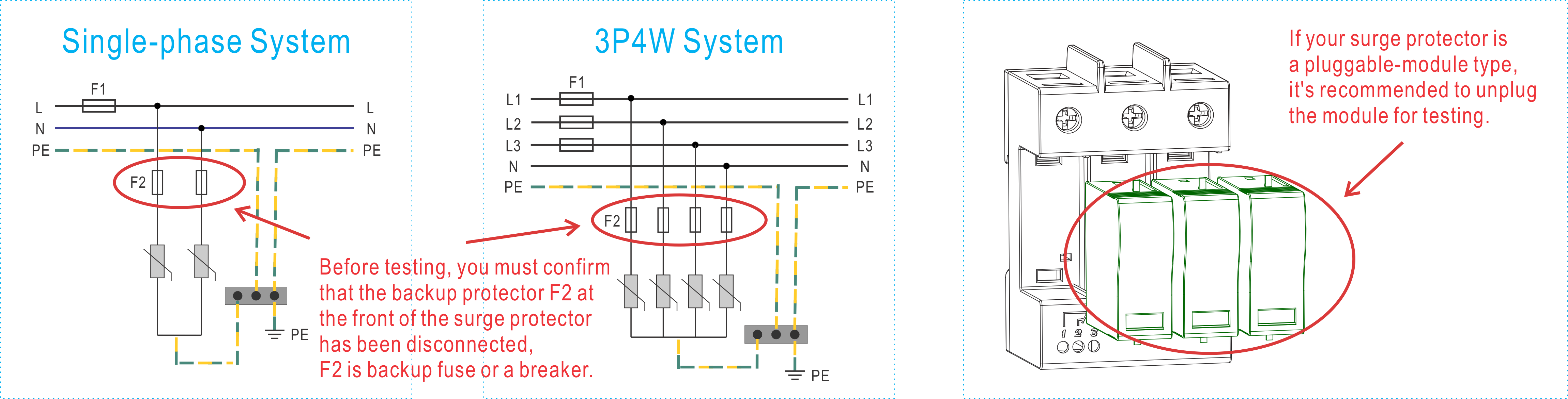
A surge protector cannot be tested under the power-on condition. It’s required to disconnect the circuit breaker or air circuit breaker at the front of the surge protector to confirm that the surge protector has been disconnected from the power grid, or unplug the surge protector module for testing. During the test, a break-over voltage is applied to the surge protector until it reaches the level of break-over status. If the live test is carried out, the product will be discharged to the ground once, resulting in the risk of short-circuiting.
5. Can the tester use rechargeable batteries?
You can use 5 pieces of rechargeable batteries instead of regular No.5 batteries.
6. Why the tester always emits an audible alarm during testing?
Check if the preset value of the break-over voltage has been set by mistake, view details on related page: Test with preset value of the turn-on voltage (Page 09)
7. Can the tester use the power bank to power the device?
You can use 2.1A output power bank to power the device
8. How is the portability of the tester?
Take an example for you to understand its its portability: when you test with a surge protector in a new building, the building is not yet powered with all plugs unpowered. WTH-CS / BT-1000V tester is powered with regular No. 5 batteries. The battery-powered tester will not affect testing work in such situation. The weight of the tester is only 570g. It is very convenient to carry it with you.
9. How many times can 4 AA batteries be tested?
We simulated testing in the laboratory. The break-over voltage of the tested surge protector was 620V. The test started testing with 4 new No. 5 batteries installed until the tester showed LOBAT low voltage alarm. The following are the results of the simulation test:
(1) On 1st day, install 4 new No.5 batteries, the display shows voltage 6.4V. After being tested 2300 times, the display shows voltage 5.3V.
(2) On 2nd day, turn on the tester, the display shows voltage 5.6V. After being tested 2200 times, the display screen shows voltage 4.9V.
(3) On 3rd day, turn on the tester, the display shows voltage 5.2V. After being tested 1300 times, the tester shows LOBAT, the display shows voltage 4.6V.
Note: The quality of the battery performance will also affect the number of tests
10. Is there a tool bag for the tester?
There is no standard kit sold with the device, you can buy a mini tool bag from us, article number: XCW8205, as shown below:
11. Can the tester measure the parameters of In, Imax, Up under 8/20μs waveform?
These parameters are not measured with this tester, but with an 8/20μs impact table and an oscilloscope. You can take samples to our factory laboratory for testing.
12. Can the tester measure the parameters of Iimp and Up under 10/350μs waveform?
These two parameters are not measured with this tester, they are measured with a 10/350μs impact table and an oscilloscope. You can take samples to our factory laboratory for testing.
13. What are the requirements of the multimeter used for calibration?
The upper limit of the voltage measured by the multimeter should meet 1000VDC, and the measured voltage accuracy is 0.1V
Measuring current accuracy 0.1μA
14. If the multimeter used for calibration is only 600V, how can I operate the calibration?
It is recommended that the upper limit of the voltage measured by the multimeter should meet 1000VDC. Reasons: The intermediate value of break-over voltage for UC385 is 620V. If the highest measured voltage of the multimeter is 600V, the varistor value selected for calibration should be within 600V.
15. How is the five-year warranty of the tester defined?
You must be the original owner of the tester and enjoy free warranty service for up to 5 years from the date of shipment.
The following list is not covered by the free warranty:
(1) Free accessories
(2) Conventional measurement services
(3) Regular calibration service
(4) Wear of product appearance in use
(5) Equipment failure caused by improper use
16. Why can't the tester test without a tested item?
When testing without a tested item, the tester will step up to the limit value because there is no load. If no-load test is carried out for many times, the boost module may be damaged. The damage of the booster module belongs to equipment failure caused by improper use and is not included in five-year warranty policy.
17. Is regular annual measurement necessary?
It depends on your own actual situation. For example, in many standards such as ISO9001, instruments and equipment are required to have annual measurement certificates.
18. Is routine calibration necessary?
If the measurement result is acceptable, then there is no need to calibrate the tester.