WTH-40/C/R/2P RS485WTH-40/C/R/3P RS485WTH-40/C/R/4P RS485  

MENU

www.watchfuleyesolutions.com - Page menu - Back to TOP -

Paperless Datasheet
Going green and protecting environment is manufacturers' responsibility. Each WatchfulEyE product has a link of downloading data sheet on its enclosure:
http://datasheet.watchfuleyesolutions.com/USR120055.html

Model & Ordering Code

Model MCOV/Uc Ordering Code Combination
WTH-40/C/R/4P-150 RS485 150VAC USR120053 4P + RS485
WTH-40/C/R/4P-275 RS485 275VAC USR120054 4P + RS485
WTH-40/C/R/4P-320 RS485 320VAC USR120055 4P + RS485
WTH-40/C/R/4P-385 RS485 385VAC USR120056 4P + RS485
WTH-40/C/R/4P-420 RS485 420VAC USR120057 4P + RS485


Installation Instruction
The smart surge protective devices shall be employed in a Listed enclosure or closet that is only accessible to technicians or service personnels.

Certificates of Products


www.watchfuleyesolutions.com - Page 01 - Back to TOP -

Description
In accordance with: IEC/EN61643-11 - Class II and UL1449 Type 4 Location
Location of use: branch sub-distribution boards
Plug-in module and separate base design enables convenient maintenance.
Internal thermal disconnect devices help ensure safe or at end-of-life
WTH-40/C/R/4P Series Technical Data
Requirement Class to IEC/EN61643-11 Class II
IEEE Category Rating B & A
Nominal Discharge Current (In) 20kA
Max. Discharge Current (Imax) 40kA
Protection Modes L-PE, N-PE
Protective Element MOV
Follow Current (If) NO
Response Time (tA) <5ns
Leakage Current (at 75%U1mA) <20μA
Thermal Protection YES
Protection Rating (IP Code) IP 20
Short Circuit Current Ratings (SCCR) 25kA rms
Max. Back-up Fuse (if mains >80A) 80A gL (circuit-breaker: <40A)
Surge Life at 3kA (8/20μs) >5000 events
Temperature Range - 40°F to 176°F (-40°C to 80°C)
Relative Humidity 0% to 95% noncondensing
Maximum Operating Altitude 10,000 feet (3000m)
Terminal Cross Section 35mm² (solid) / 25mm² (stranded)
Stripping Length Contacts 0.6inches (15mm)
Terminal Screw Torque Max. 3.5Nm
DIN Rail EN60715 35mm top-hat rail
Dimensions DIN 43880 90mm (5TE)
Housing Material Thermoplastic (UL94 V-0)
Housing Design Modular design
Net Weight Per Unit 1Lb (450g)

www.watchfuleyesolutions.com - Page 02 - Back to TOP -
.

Surge Protection Connection Diagram


Maximum Continuous Operating Voltage (MCOV/Uc) 150VAC 275VAC 320VAC 385VAC 420VAC
Voltage Protection Level (Up) 1.3kV 1.5kV 1.7kV 1.8kV 1.9kV
Residual Voltage (Ures) 0.8kV 1.0kV 1.1kV 1.2kV 1.4kV


Dimensions


www.watchfuleyesolutions.com - Page 03 - Back to TOP -
.

Fault Indication (same indication in 2P/3P/4P models)


www.watchfuleyesolutions.com - Page 04 - Back to TOP -

Common Terms and Definitions
1. Normal operating voltage rating (Un)
2. Maximum Continuous Operating Voltage (Uc/MCOV):
Maximum r.m.s. voltage, which may be continuously applied to the surge protective device's mode of protection.
3. Nominal Discharge Current for Class II Test (In):
crest value of the current through the surge protective device having a current waveshape of 8/20μs.
4. Maximum Discharge Current (Imax):
Crest value of a current through the surge protective device having an 8/20μs waveshape and magnitude according to the manufacturers specification. Imax is equal to or greater than In.
5. Voltage Protection Level (Up):
Maximum voltage to be expected at the surge protective device terminals due to an impulse stress with defined voltage steepness and an impulse stress with a discharge current with given amplitude and waveshape.
6. Residual Voltage (Ures):
Crest value of voltage that appears between the terminals of an surge protective device due to the passage of discharge current.
7. IEEE 62.41
CATEGORY C: outdoor overhead lines, service entrance (most severe)
CATEGORY B: major feeder, short branch circuits, service panel (indoor)
CATEGORY A: long branch circuits, receptacles (indoor) (least severe)

How to choose a suitable Uc(MCOV) value
Note: Uc >1.15Un
The relationship between two parameters Uc and Up of a surge protective device is proportional.
If Uc is small, the value of Up is also small; surge protective devices with smaller Up can provide better surge protection.
Whether to choose smaller Uc depends on the voltage stability of the grid.
If you choose surge protective devices with smaller Uc for the grid with instable voltage, the surge protective devices will frequently work while the grid voltage fluctuates, resulting in shortening surge protective device's product life.
If you choose larger Uc, and the value of Up is accordingly large, the surge protective efficiency will not be so fine.
If you are unsure of the voltage stability of the grid,
it is suggested to calculate MCOV(Uc) using the following formula: √ 2  Un < Uc < √ 3 Un

AC Network (Un) MCOV(Uc), L/N-PE Protection Mode
110V, 120/208V, 127/220V 150V
220/380V 275V, 320V, 385V
230/400V 275V, 320V, 385V, 420V
240/415V 320V, 385V, 420V
266/460V, 277/480V 385V, 420V
347/600V 550V, 690V
Wind Power System 690V (Grid side ), 885V (Gen side )

www.watchfuleyesolutions.com - Page 05 - Back to TOP -
.

AC Network Connection Diagram (1/2)


www.watchfuleyesolutions.com - Page 06 - Back to TOP -
.

AC Network Connection Diagram (2/2)


Difference mode & Common mode Connection Diagram


Common mode:L-PE, N-PE surge protection
Difference mode:L-N surge protection

www.watchfuleyesolutions.com - Page 07 - Back to TOP -
.

Selection of back-up fuse

Selection of back-up circuit-breaker

www.watchfuleyesolutions.com - Page 08 - Back to TOP -
.

Application


Key
1. Origin of the installation
2. Distribution board
3. Distribution outlet
4. Main earthing terminal or bar
5. Surge protective device, class I or II tested
6. Earthing connection (earthing conductor) of the surge protective device
7. Fixed equipment to be protected
8. Surge protective device, class II tested
9. Surge protective device, class II or class III tested
10. Decoupling element or line length
F1, F2, F3 overcurrent protective disconnectors
NOTE Refer to IEC 61643-12 for further information.

www.watchfuleyesolutions.com - Page 09 - Back to TOP -

Application Range
Surge counter is used to test and record the discharge frequency of the surge protector ( record the surge current rush frequency beyond certain degree) and SPD remote contacts monitoring, which is convenient for users to do statistics and analysis on the surge situation in specific area.
It can be used accompanying with various surge protectors or used as the supported product of the surge protective box.
In accordance with: IEC 62561-6:2018 --- Lightning protection system components (LPSC) - Part 6: Requirements for lightning strike counters (LSC)

Main Features
1. Large counting range, wide application range
2. Sensitive response, precision counting, no mis-operation
3. 3-bit digital display, easy and clear to recognize
4. No data loss in case of power outages
5. DIN-rail installation, convenient for installation and replacement
6. Adopting single-chip technology, advanced and reliable structure
Surge Counter Technical Data
Effective action current >1kA
Max. discharge current (8/20µs) 80kA
Sampling mode Inductance coil
Counting number 0~999
Rating Voltage USB (DC5V)
Terminal Cross Section Max. 1.5mm²
Stripping Length Contacts 0.25 inches (6-7mm)
Terminal Torque 0.25Nm

www.watchfuleyesolutions.com - Page A1 - Back to TOP -
.

Detector Status Description


Power (green): Power indicator, when the power is turned on, the indicator light is on
Data (orange): Data sending indicator, when there is data sending, the indicator flashes
Alarm (red): The alarm indicator light, or when the number of surges increases, keeps on, press the Reset button to reset the light off; when the surge protector failure is detected, it keeps on

www.watchfuleyesolutions.com - Page A2 - Back to TOP -
.

LCD Display Description


LCD display 0-9 numbers and A-F letters, check the following table:

Modbus Mode: RS485 ID, Surge Counts
I. Turn on the power, the LCD screen first displays the RS485 address (factory value 001), and then displays the number of surges, the screen keeps displaying this value


II. Continuing pressing RESET to enter SETTING status. When the Alarm light flashes frequently, continue pressing it, the indicator light loops from bottom to top.

www.watchfuleyesolutions.com - Page A3 - Back to TOP -
.

Setting Steps


1. When ALARM indicator flashes frequently, short press RESET, switch to NO/NC, default: 0 (NO: normal, NC: fault)


2. When Modbus indicator flashes frequently, short press RESET to set RS485 ID address (RS485 ID: 1-247)


3. When POWER indicator flashes frequently. Short press RESET to save data and return to the Standby mode. (Data can also be saved automatically after 30 seconds and return to Standby mode without pressing RESET in any setting status)

Cloud Service Mode: Device ID, Surge Counts
When the power is turned on, the LCD screen displays in sequence: the first screen displays 2 digits or letters, the second screen displays 3 digits or letters, and the third bottle displays 3 digits or letters, and the device number consisting of 8 numbers or letters in total ( Take the device number 2010CAFE as an example: the first screen displays 20, the second screen displays 10C, and the third screen displays AFE)
After the three screens are displayed, the last display is the number of surges, and the screen keeps displaying this value.
(Each product has a unique Device ID, which is fixed in the product when it leaves the factory. This device number is only used for Cloud service functions)

www.watchfuleyesolutions.com - Page A4 - Back to TOP -
.

Connection Diagram


Power supply (100-240VAC or USB-5VDC):
When the L-N power cord is connected, the LED light is on (you can also choose to connect the USB power adapter)


www.watchfuleyesolutions.com - Page A5 - Back to TOP -
.

Inductance Coil Connection Diagram

www.watchfuleyesolutions.com - Page A6 - Back to TOP -
.

Inductance Coil Connection Diagram


A: If the grounding wire can penetrate the magnetic ring, and Imax of the surge protector is less than 80kA
B: If the grounding wire cannot penetrate the magnetic ring, or Imax of the surge protector is greater than 80kA, use the shunt connection method

www.watchfuleyesolutions.com - Page A7 - Back to TOP -
.

Server Modbus Networking System Diagram


Test Steps
Step 1: Modbus (Page A6)
Step 2: USB Power (Page A6 | Page A7)
Step 3: NO/NC (Page A5)
Step 4: RS485 ID (Page A5)
Step 5: RS485 connected to the computer (Page A6 | Page A7)
Step 6: Download software
Step 7: Test read data

www.watchfuleyesolutions.com - Page B1 - Back to TOP -
.

Communication Protocol: Modbus RTU
Baud rate: 19200 (Customized: 4800/9600/19200/38400)
Data bits: 8 bit
Parity Check: none
Stop bit: 1 bit

03 Read Holding Register
Address Description Read/Write Data Type Length
0 System reservation R Integer 1
1 Device address high position R Integer 1
2 Device address low position R Integer 1
3 System reservation R Integer 1
4 Cloud service data sending cycle R/W Integer 1
5 Surge count value R Integer 1
6 RS485 working mode (0:modbus 1:cloud) R Integer 1
7 Modbus address R Integer 1
8 Modbus baud R Integer 1
9 SPD remote communication state (0:Normal open 1:Normal close) R Integer 1
10 SPD Remote Alarm mode (0:NC Alarm 1:NO Alarm) R/W Integer 1
11 Device state (0:Normal 0xffff: Alarm) R Integer 1

www.watchfuleyesolutions.com - B2 - Back to TOP -

FAQ & Help (1/2)
1. What should I do if I can't find the paper manual in the product packaging?
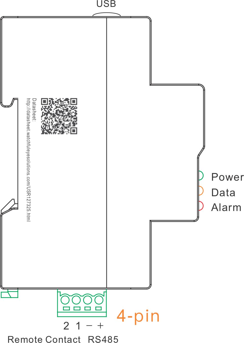
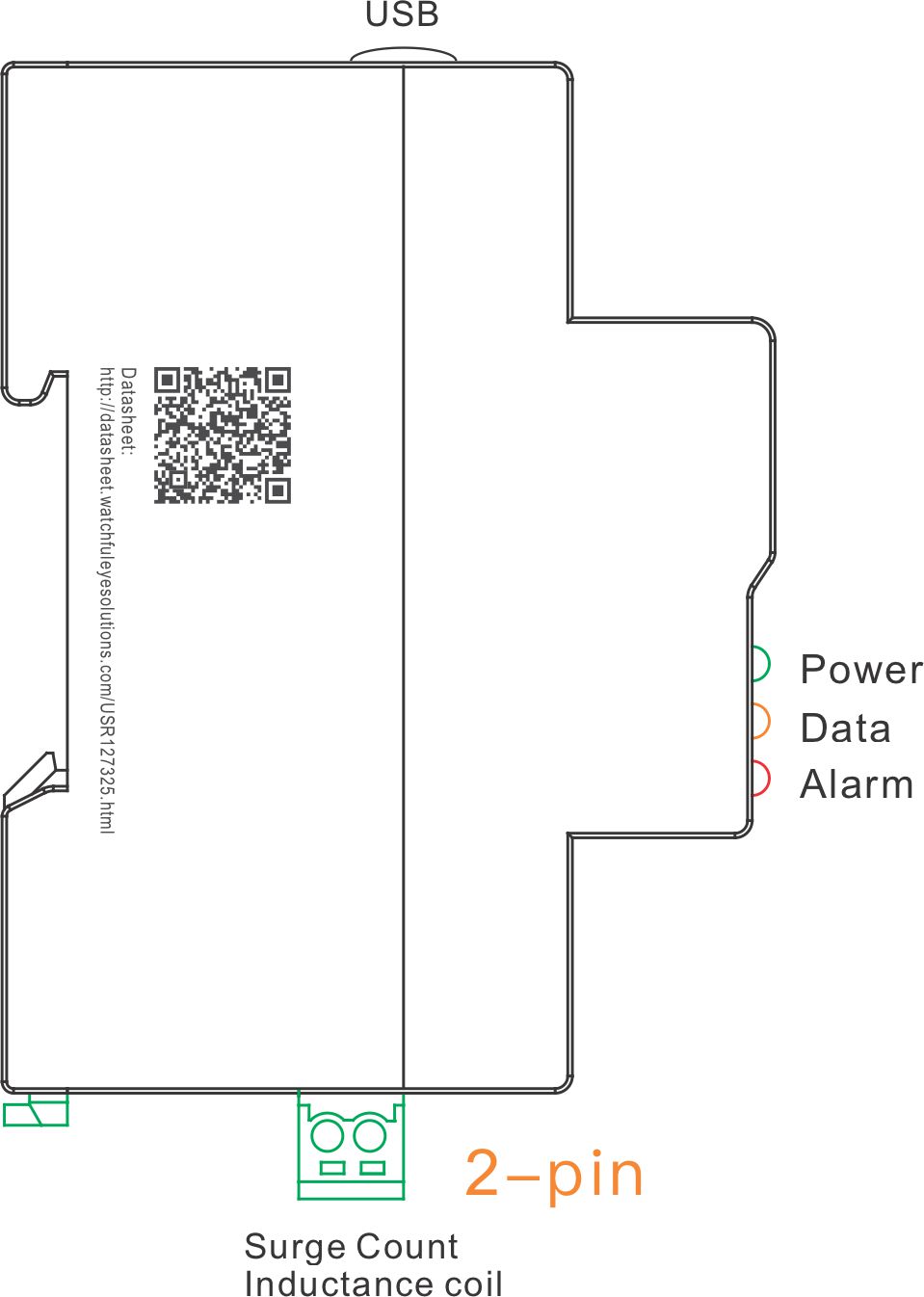
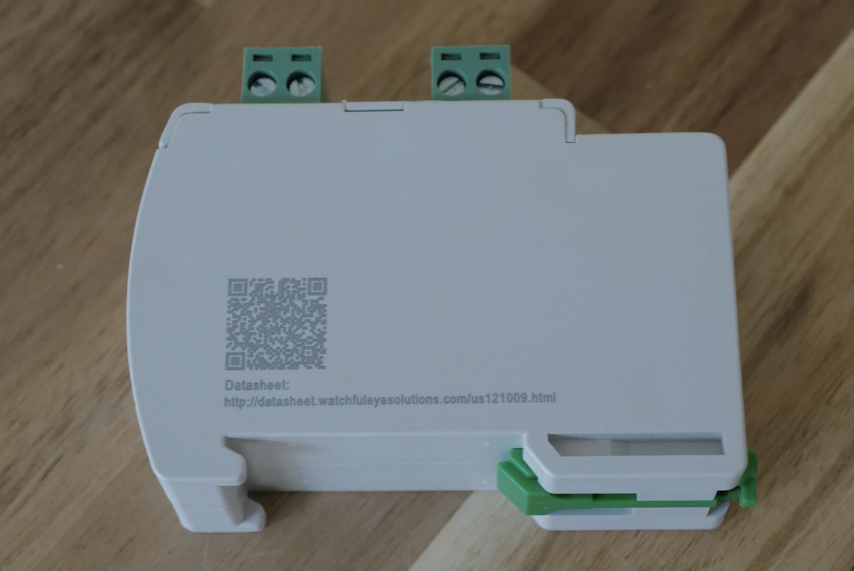
Watchful Eye products is committed to going green with paperless data sheets. On the left side of each product enclosure is an engraved link with URL for downloading paperless data sheet and QR code of the website. If you need the paper data sheet, you can open the link and print the data sheet by yourself.


2. Some questions about Product Serial Number
a. Each product has a unique product serial number, and the barcode is laser engraved on the side of the product when it leaves the factory, for example: S.N.: USR127325-7AG002
b. This serial number is a certificate for tracking product warranty and service
c. In the Cloud Service function, the serial number is the server login password initialized at the factory, and the password can be changed after login.

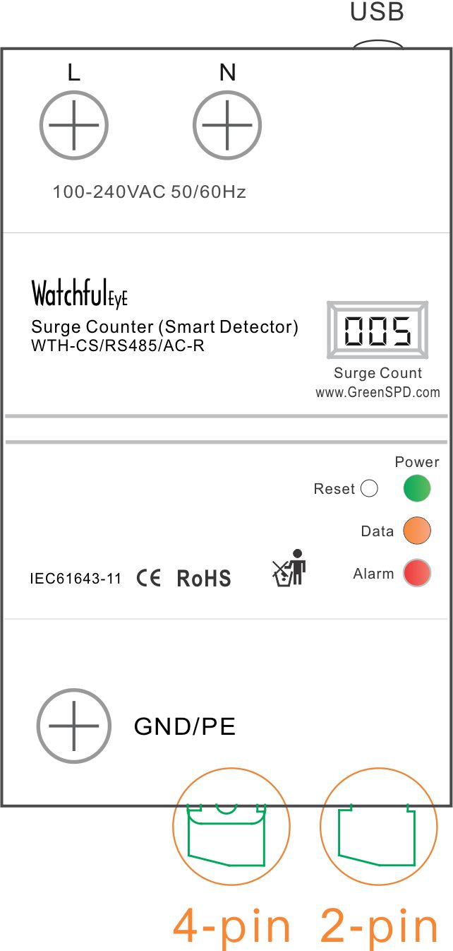
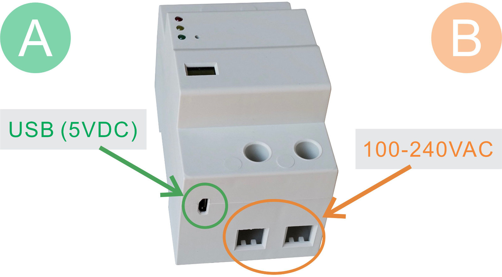
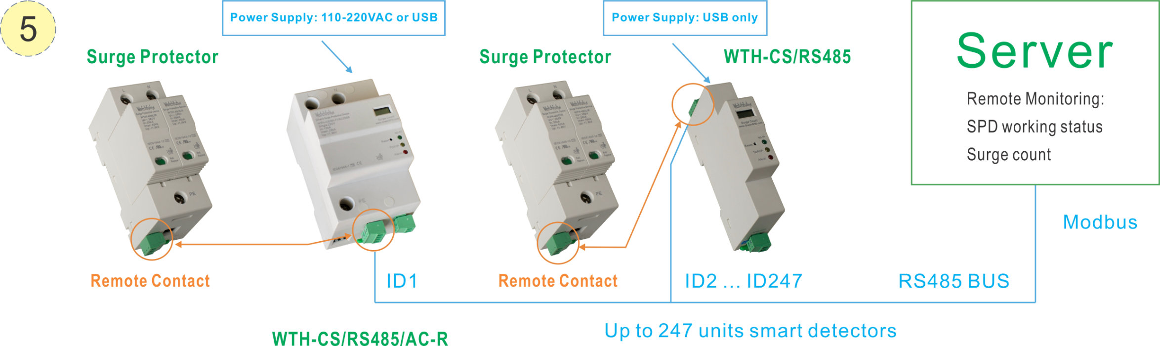
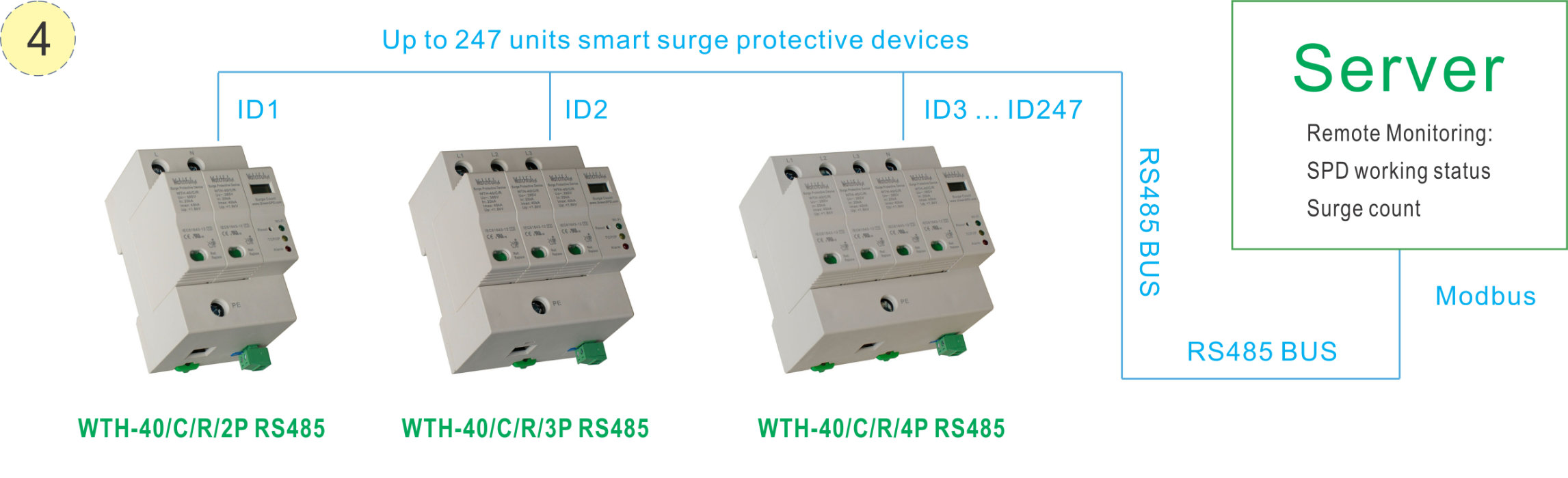
3. Why does the surge count monitoring module need a separate USB power supply?
According to the requirements of the UL test standard, the power supply of the surge protector module needs to be connected to an independent group to ensure the safety and reliability of the system.


www.watchfuleyesolutions.com - Page C1 - Back to TOP -

FAQ & Help (2/2)
4. I have question for Surge Counter how the minimum of Input Current for testing?
Surge count test of minimum input current:
It is tested in the factory with a 1.2/50μs + 8/20μs combination wave generator
If it is only to test the digital display of the surge count, a 10μF 400V capacitor can be used, refer to the following steps
Note: This method cannot simulate 8/20μs surge waveform.


Step 1: Turn on the power switch to charge the capacitor for 1 second
Step 2: Turn on the power switch to make the capacitor short-circuit discharge


www.watchfuleyesolutions.com - Page C2 - Back to TOP -

Download WatchfulEyE Official App
To learn about more products and updates from company, please scan QR code to download the official App:

After-sale Services
Watchful Eye provides a 5-year quality warranty globally.


I have a question

www.watchfuleyesolutions.com - Page C3 - Back to TOP -
.

Monitoring Server Network System Diagram


Combined Model
Model Ordering Code UPC/EAN Code
WTH-CS/F-D USR127209

Server Modbus Networking System Diagram


www.watchfuleyesolutions.com - Page D1 - Back to TOP -